|
tbone
|
 |
« on: November 27, 2008, 07:14:31 AM » |
|
You`ll have read about it, you`ll have seen pictures of it and if your really lucky, might have even seen it in the flesh! The Manky Monkey Motors Caliper Conversion! Now you may even be wondering to yourselves, how do i do that? Well, make a cuppa (two sugars in mine please), sit back and read on, and i`ll try to show you, how, with just basic hand tools, you can craft the caliper mounting bracket.
|
|
|
|
« Last Edit: November 27, 2008, 05:10:26 PM by tbone »
|
 Logged
|
NO I WON`T. aye ok then, i will
|
|
|
|
tbone
|
|
« Reply #1 on: November 27, 2008, 07:28:43 AM » |
|
Firstly, gather together a few basic tools. An electric drill, an assortment of drill bits,a jigsaw, a grinder,a hammer, a centre punch, a ruler, a file and a set of compasses. Put it all on your work area ready then tootle off and find yourself some steel plate. I picked mine up from a local engineering company, i went along and told the guy i was after some 6mm plate 5" x 6", i was lucky enough for him to cut me two pieces for free, although i`d have happily paid.
Next, print off the template that`s floating around here somewhere on another thread, cut it out and stick it onto your steel plate.
|
|
|
|
« Last Edit: November 27, 2008, 08:12:16 AM by tbone »
|
Logged
|
NO I WON`T. aye ok then, i will
|
|
|
|
tbone
|
|
« Reply #2 on: November 27, 2008, 07:39:03 AM » |
|
Now we need to mark it out, for this you`ll need your centre punch. Put it onto the centre of the holes, marked on the template and whack it with a hammer, this will leave a nice little indent on your steel plate that marks out the hole centres, now you can use your punch as a scribe and "draw" around the outside of the template to mark out the shape. When thats done it should look something like the picture below.
|
|
|
|
|
Logged
|
NO I WON`T. aye ok then, i will
|
|
|
|
tbone
|
|
« Reply #3 on: November 27, 2008, 07:51:02 AM » |
|
Next, insert a 2mm drill bit into your drill and drill all the indents that you just marked out. The 2mm hole will not only allow you to see the hole centres more easily but will also act as a pilot hole for when we have to make those holes bigger, but we wont do that yet. What we do next is mark out the large hole in the middle, 47mm. To do this, take your punch and secure it into your compass,measure half the diameter, 23.5mm, and then mark this onto your plate.
|
|
|
|
|
Logged
|
NO I WON`T. aye ok then, i will
|
|
|
|
tbone
|
|
« Reply #4 on: November 27, 2008, 08:10:01 AM » |
|
Now we can drill the holes out to the correct sizes, with a new drill bit, the 8mm holes are easily done, for the 12mm holes its best to drill these to 8mm then using progressivly larger bits drill them out to 12mm.
Just a quick point about working with 6mm plate, its thick. When drilling (or cutting) dont just pull the trigger and allow your drill to spin away at top speed, This will make it all very hot, will blunt your drill bit and may cause you to slip. Start slowly, allow the bit to bite into the steel and continue at a steady pace, your drill has that wheel, knob, button or whatever speed setting device for a reason......use it.
This next step is probably the hardest, not that its difficult but it is time consuming and involves the most work. Yep we gotta cut the big hole out, remember we are only using basic hand tools so no holesaw or lathe! So how do we do it? We drill lots of holes just inside of the marked out circle, then we join those holes up by dirlling one of them out larger and using a jig saw, cut out the centre.
|
|
|
|
« Last Edit: November 27, 2008, 10:05:46 AM by tbone »
|
Logged
|
NO I WON`T. aye ok then, i will
|
|
|
|
tbone
|
|
« Reply #5 on: November 27, 2008, 08:20:58 AM » |
|
Ok, clean up the sharpe edges of the large hole with your file and its starting to come together. If, like me, you find that filing is a pain, you can use those grinding stones that fit to your drill. They will do the job but generally take 4 times as long! So now you`ll have something that looks like this.
|
|
|
|
|
Logged
|
NO I WON`T. aye ok then, i will
|
|
|
|
tbone
|
|
« Reply #6 on: November 27, 2008, 08:29:05 AM » |
|
Hmmm, dont look much, just a collection of holes! Time to put some shape to it i think. Fire up your grinder,(i used a bench mounted one but you can use an angle grinder) and grind the corners off to the shape we marked out.
|
|
|
|
|
Logged
|
NO I WON`T. aye ok then, i will
|
|
|
|
tbone
|
|
« Reply #7 on: November 27, 2008, 09:23:06 AM » |
|
Nearly there now! Lets cut the rest to shape, this can be done with a cutting disc in your grinder but i found it neater to use the jigsaw. With the plate securely clamped in place, using the lowest speed setting and a 21 or 24tpi blade, its an easy job to cut the final shape with a jigsaw, following the outline we previously scribed out. Take your time with this and let the blade do the work, its 6mm steel plate that your cutting so its not gonna slice through it but it will do the job.
|
|
|
|
« Last Edit: November 27, 2008, 09:56:21 AM by tbone »
|
Logged
|
NO I WON`T. aye ok then, i will
|
|
|
|
tbone
|
|
« Reply #8 on: November 27, 2008, 09:38:09 AM » |
|
Quick clean up with the grinder and there you have it, one bracket, now do it all again for the second one! Not cut on a lathe or using CNC but all done in my shed using basic tools, a little bit of time and minimal sweat! Now if you can get them machined up by your local engineer then thats fine, but if not, you can always do them yourself!
|
|
|
|
|
Logged
|
NO I WON`T. aye ok then, i will
|
|
|
|
tazet
Guest
|
|
« Reply #9 on: November 27, 2008, 02:38:21 PM » |
|
That's great Mr Tbone. Have you got some good quality photos so I can add it to the relevant section on the main site.
|
|
|
|
|
Logged
|
|
|
|
triker9999
Sr. Member

Karma: 8
Posts: 306
|
|
« Reply #10 on: November 27, 2008, 03:01:20 PM » |
|
informative and easy to follow, just what we like Proffessor T Bone
will come in handy i hope!!
|
|
|
|
|
Logged
|
The last words spoken by Union General John Sedgewick were, They (the Confederate soldiers) couldnt hit an elephant from this dis
|
|
|
Manky Monkey
Administrator
Hero Member

Karma: 264
Posts: 55102

|
|
« Reply #11 on: November 27, 2008, 06:50:52 PM » |
|
Well done TB. An idiot's guide -if an idiot like me can do it, anyone can! Nothing to add, except that the posh CNC machined plates that SaddleBags produced for us were done in 10mm aluminium plate with a machined recess that sits over the end of the axle tube, so that the plates are effectively 7mm. All you need to do is centralise the caliper over the disc, so if you used 5mm plate you could add a thick washer between caliper & plate to space it out. A couple of the calipers we've had don't appear to sit squarely over the disc, so that one corner of the pads rub very slightly. Strategic use of spacer washers easily cures this. Just common sense stuff really. Oh & I prefer to use a white "Tippex" correction pen rather than a scribe to mark out metal, as it shows up much clearer once you start grinding or jigsawing. As Taz said, we'll add this to the main website. Thanks TB. If anyone else fancies sharing their workshop secrets with us, drop us a line at the email address on the Contacts page of the main site or PM us here. Remember, not everyone has spent their lives tinkering in workshops. What seems blindingly obvious to you may be just the revelation someone else is looking for. None of us is too clever to learn something new.  |
|
|
|
|
Logged
|
On the last freedom moped out of Nowhere City.
|
|
|
|
Hagar
|
|
« Reply #12 on: November 27, 2008, 08:45:10 PM » |
|
Evening , nice one ... clear and easy to follow and with piccies  ( I do like a piccie ) .... I've used the small holes and jig sawed ( or waggled the drill bit about to open out the holes ) method on wood and thin plate , never thought about doing it on 6mm plate though ..... looks good . I got my plates and hubs back on monday ..... , took about 5 weeks to get them back  , seems everywhere they went as soon as they said it was for a trike nobody wanted to do them ... something about liability for automotive parts ( thats what they told me anyway , and before you ask I dont want to buy tower bridge ... I already bought that last week  ) , they said they told the last guy that the bits were from a french conveyer system .. 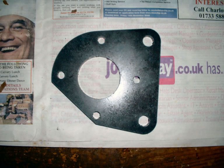 Manky Motors Caliper Mounting Bracket and 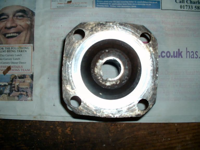 Manky Motors Caliper Mounting Bracket Not got the bill yet though , just got to dremel up the calipers and carriers .. a splash of paint then stick it all back together ...  cheers .. Hagar |
|
|
|
|
Logged
|
" When you have to kill a man , it costs nothing to be polite. " .. Winston Churchill
|
|
|
|
tbone
|
|
« Reply #13 on: November 27, 2008, 09:12:04 PM » |
|
One more conversion done by the weekend then . Looks like your going for the thicker wheel studs too? |
|
|
|
|
Logged
|
NO I WON`T. aye ok then, i will
|
|
|
Manky Monkey
Administrator
Hero Member
Karma: 264
Posts: 55102
|
|
« Reply #14 on: November 27, 2008, 10:05:13 PM » |
|
That grinning guy on the newspaper's kinda scary!
Sounds like we're on a mission to convert every Reliant in the country to discs!
|
|
|
|
|
Logged
|
On the last freedom moped out of Nowhere City.
|
|
|
|


